An RFID card looks like an ordinary plastic card, but it is a small radio system with no battery inside. Hold it near a reader and a door opens, a turnstile releases, or a payment terminal responds. This guide explains what is happening: the two parts inside the card, how the card and reader exchange data without contact, and why that design replaced the magnetic stripe. If you are specifying an order rather than studying the physics, the closing section covers what these mechanics mean for a purchase.
Table of Contents
What is inside an RFID card
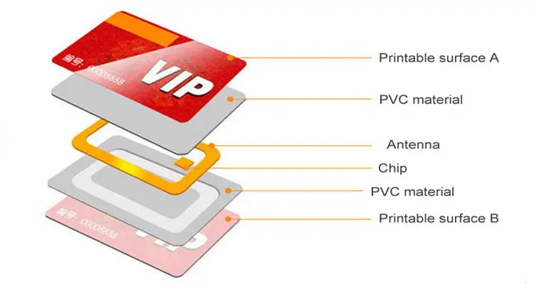
A passive RFID card contains only two working parts, joined into a single unit called an inlay:
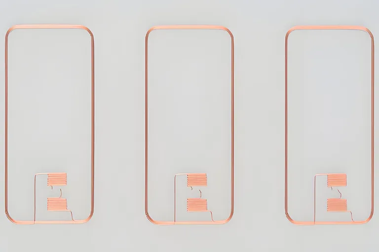
- An antenna coil — a flat loop of thin copper or aluminium wire, laminated between the plastic layers. It does two jobs: it captures energy from the reader’s field to power the chip, and it carries the chip’s reply back to the reader.
- A microchip (the integrated circuit) — a silicon chip bonded to the ends of the antenna. It holds the card’s unique identifier (UID) and any application data, and it runs the small amount of logic needed to answer the reader. Its memory is non-volatile, so the data survives when the card leaves the field.
Everything else is packaging. A standard card is the ISO/IEC 7810 ID-1 format (85.6 × 54 mm, nominally 0.76 mm thick), built from PVC, PET or another body material such as PLA, wood or paper, with the inlay sealed between printed outer layers under heat and pressure. The artwork on the surface has no effect on how the card is read, provided the antenna is tuned for the chosen body material and thickness. That is why a wooden or metal card can behave differently from plain PVC and needs its own antenna design — the electronics are the same idea, but the tuning is not.
There is no battery, no button and no display. The card does nothing at all until a reader supplies it with power.
How the card and reader exchange data
The exchange is a short handshake that runs in a fraction of a second, faster than the gesture of tapping. It follows a fixed order:
- The reader creates a field. The reader continuously radiates an alternating electromagnetic field at the card’s operating frequency — 13.56 MHz for most smart cards under ISO/IEC 14443, or 125 kHz for older low-frequency proximity cards. The field only reaches a few centimetres, which is why you have to bring the card close.
- The card powers up. When the antenna enters that field, it captures energy by induction — the same principle as a wireless phone charger. The card rectifies that energy into a working voltage and the chip comes to life on borrowed power.
- The reader sends commands. The reader varies its field to send instructions: identify yourself, authenticate, read or write a specific memory area.
- The card replies by load modulation. This is the part that surprises people. A passive card has no transmitter and no power to run one, so it does not broadcast. Instead it changes how much energy it draws from the reader’s field, in a controlled pattern. The reader senses those tiny variations in its own field and decodes them as the card’s answer.
- The exchange ends. Once the identifier, authentication and any data operations are complete, the card leaves the field, loses power and holds its data until the next read.
When several cards sit in the field at once, the protocol runs an anticollision step so the reader can single out and address each card in turn rather than hearing a jumble. That is what lets a reader resolve one card cleanly even when a wallet holds two.
What is ISO/IEC 14443?
ISO/IEC 14443 is the international standard for contactless proximity cards and their readers at 13.56 MHz. It covers the card itself, the radio interface, how a reader wakes and selects one card among several, and the protocol that carries commands. It has four parts and two signalling variants, Type A and Type B. The standard calls the card a PICC (proximity card or object) and the reader a PCD (proximity coupling device).
| Part | Title | What it settles |
|---|---|---|
| 14443-1 | Physical characteristics | Physical characteristics of the card or object, including its antenna size |
| 14443-2 | Radio frequency power and signal interface | The 13.56 MHz carrier, modulation and coding, field-strength limits; split into Type A and Type B |
| 14443-3 | Initialization and anticollision | How the reader polls, how a card answers, and how one card is selected among several |
| 14443-4 | Transmission protocol | The block protocol for the data exchange, often called T=CL |
The handshake above maps onto these parts (summarised from the ISO pages and NXP’s application note AN10833): the field and load modulation are Part 2, anticollision is Part 3, and on chips that use it, commands travel over Part 4.
Type A and Type B
Both types use the 13.56 MHz carrier; they differ in modulation and coding (Part 2) and in the start-up and anticollision sequence (Part 3). NXP’s MIFARE and NTAG chips identify themselves through the Type A sequence, which AN10833 calls the MIFARE variant, so the MIFARE, NTAG and DESFire cards we list are all Type A. If your reader, scheme or existing cards use Type B, say so in the inquiry so we can check whether a matching chip is available before quoting.
What “ISO 14443 compliant” does not tell you
Compliance can stop at Part 3. According to AN10833, every MIFARE chip complies with Parts 2 and 3, but only some support the Part 4 protocol, among them DESFire and MIFARE Plus in Security Level 3. MIFARE Classic runs NXP’s native command set on Part 3 with its proprietary CRYPTO-1 authentication. DESFire EV2, by contrast, is compliant with all levels of 14443 Type A and supports optional ISO/IEC 7816-4 commands (NXP datasheet). In practice:
- A reader sold as “ISO 14443” may read a Classic card’s UID but not its sectors; that needs Classic command support. See MIFARE Classic cards.
- The standard does not define your application. File layout, keys and access rules sit above it, set by the system and by whoever encodes the cards.
- Read distance depends on the reader and the antenna. NXP quotes up to 100 mm for DESFire EV3, depending on reader power and antenna geometry; a finished card’s range also depends on its own antenna and body.
Passive by design: no battery on the card
The cards in almost every access, hotel, transit and payment system are passive: no onboard power source, energised only while inside a reader’s field. That is a deliberate choice. A passive card has nothing to wear out or run flat, costs far less to make than a powered device, and can be laminated flat enough to print and carry in a wallet.
For contrast, active tags carry a battery and their own transmitter, which buys long range and features such as sensors — at the cost of size, price and a finite battery life. Battery-assisted (semi-passive) tags sit between the two. Ordinary RFID and NFC cards are firmly in the passive camp, which is exactly why they are cheap, durable and maintenance-free. For a side-by-side table, see active vs passive RFID.
Why RFID replaced the magnetic stripe
A magnetic stripe stores a fixed pattern that a reader plays back on contact. An RFID card holds a chip that can authenticate and, on the more capable families, run a live cryptographic exchange. Several practical differences follow from that:
- No physical contact, so no wear. There is no head to grind against and no stripe to demagnetise, so a card tolerates far more use before it fails.
- Tolerance to dirt and weather. A card reads through a wallet, a glove or a thin layer of grime, where a dirty stripe or a scratched barcode simply fails.
- Stronger security options. A stripe, once copied, is copied forever. Modern chips such as DESFire or NTAG 424 DNA answer each read with a changing cryptographic value, which a static copy cannot reproduce. Note that this depends on the chip: a basic chip that only returns a UID offers little more protection than a stripe.
- More than one application per card. A capable chip can hold separated areas for, say, door access and cashless catering on the same card.
The stripe still appears next to the chip on some cards where a site bridges old and new readers, such as stripe-and-chip hotel keys during a lock changeover, but for new systems the chip is the credential.
Which chip is inside which card
“RFID card” is a family, not a single product, and the right chip depends entirely on the reader that has to accept it. A few common cases:
- 13.56 MHz smart cards — MIFARE Classic, MIFARE Plus and MIFARE DESFire for access and transit; NTAG NFC cards for phone-readable interactions. These use the ISO/IEC 14443 contactless interface; NTAG and DESFire are read by nearly every modern smartphone, but MIFARE Classic’s proprietary sector data is not accessible on iPhones and some Android phones.
- 125 kHz proximity cards — T5577 and EM4305/EM4200 chips for legacy door systems; our T5577 cards use Microchip’s genuine ATA5577C and our EM4305 cards genuine EM Microelectronic chips. Short range, low cost, no smartphone reading.
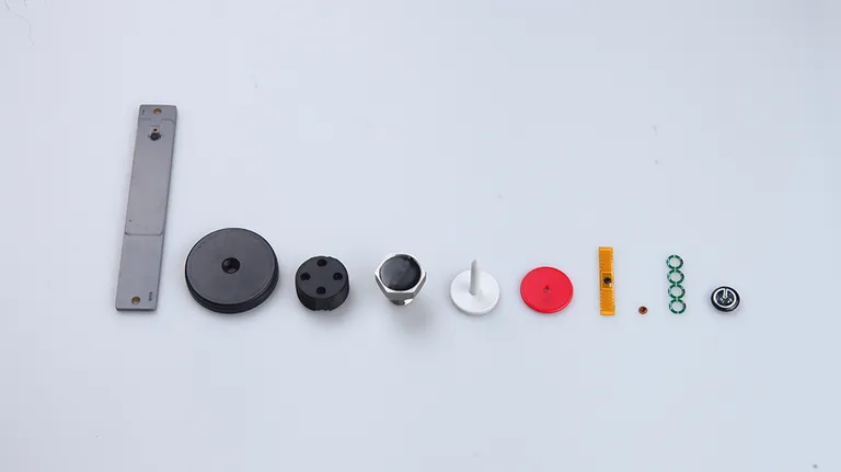
- Wooden, metal, paper and PLA bodies — the same chip families in a different material, each needing its own antenna tuning.
The card body is a design choice; the chip is a compatibility decision. The two questions to answer before ordering are which chip your readers accept and who writes the data.
What this means when you buy
The mechanics above lead to one practical rule: the buying decision starts with the reader, not the plastic. A card only works if its chip and configuration match what the installed reader expects, and the data that makes it “open the door” is written by the system, not the supplier.
When you specify an order, confirm the exact chip your readers accept, whether cards are supplied blank or pre-encoded, and who holds the keys and performs personalisation. If we pre-encode them, every card is read back after encoding and the order ships with a data report, and numbered cards come with an Excel, CSV or XML file pairing each chip ID with its printed number; the RFID encoding service sets out the rest. Then prove it before committing to a batch: request a small number of samples and test them on your own readers before approving the run. For the difference between the frequency bands, read RFID frequencies explained: LF vs HF vs UHF; for where NFC fits, see NFC vs RFID.
To move from theory to a decision, browse RFID and NFC cards, tell us the reader model and application through the inquiry form, and start with a sample pack so you can verify compatibility on your own equipment before you order in volume.
Common questions
Are 125 kHz proximity cards covered by ISO/IEC 14443?
No. ISO/IEC 14443 is a 13.56 MHz standard. 125 kHz cards such as EM4305 and T5577 are low-frequency cards read by 125 kHz readers, so a site that uses both kinds of card needs dual-frequency readers or separate readers for each.
What is the difference between ISO/IEC 14443 and ISO/IEC 15693?
Both are 13.56 MHz contactless standards, but ISO keeps them as separate series: 14443 for proximity cards used close to the reader, such as access and transit cards, and 15693 for vicinity cards and labels designed to be read from further away.
Is FeliCa an ISO/IEC 14443 card?
No. FeliCa runs at 13.56 MHz but uses its own air interface, JIS X 6319-4, included in ISO/IEC 18092 as NFC-F, so a reader built only for 14443 Type A does not read it. See FeliCa cards.
Will any ISO 14443 card work with my reader?
Not on the strength of the standard alone. Confirm the exact chip, which parts of 14443 it uses and who loads the keys, then test samples on the installed reader before ordering.