RFID Cards
Combi Card
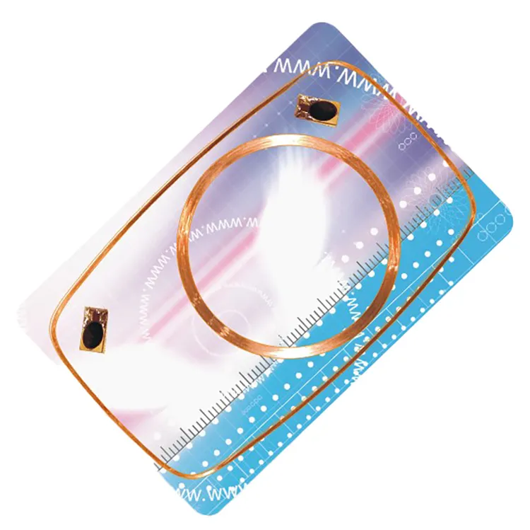
A combi card carries two or more independent chips — e.g. 125 kHz plus 13.56 MHz — so one card works on both the old system and the new one during a technology migration.
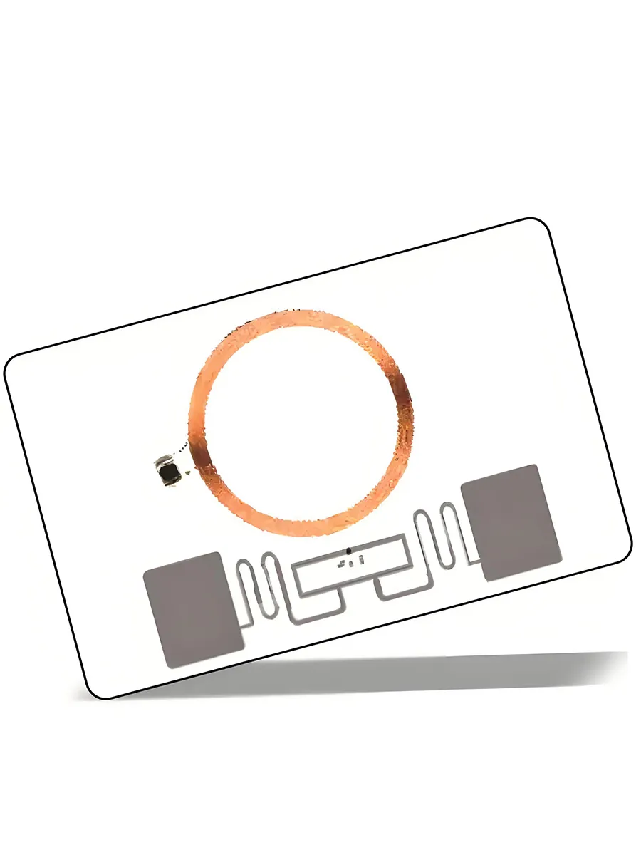
A combi card is a multi-chip card: two or more separate chips in one card body, usually contactless chips each with its own antenna, for example a 125 kHz chip with a 13.56 MHz chip, or an HF chip with a UHF chip. Each chip answers its own reader system and is specified, encoded and tested on its own, so one card can keep an installed 125 kHz system working while a 13.56 MHz or UHF system is added. Tell us each chip, its format and the reader it must work with.
Free standard samples · Quotation within one business day
Product details
What a combi card is
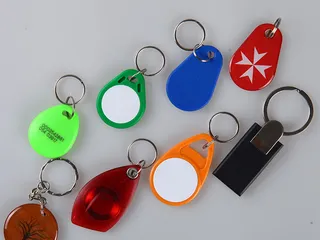
A combi card is a multi-chip card: two or more separate chips in one card body, most often two and sometimes three. Usually all of them are contactless, each connected to its own antenna and working at its own frequency. The chips are not linked: data written to one does not appear on another, and a 125 kHz reader reads only the low-frequency (LF) chip while a 13.56 MHz reader reads only the high-frequency (HF) chip. The usual pairings are an LF chip with an HF chip, and an HF chip with a UHF chip. The key-fob form of the LF + HF card is the dual-frequency key fob.
Combi card versus dual interface card
They are different products. A combi card is a multi-chip card: two or more separate chips, usually contactless, such as 125 kHz + 13.56 MHz or HF + UHF, each read by its own reader. A dual interface card is a card with a contact interface and a contactless interface, both leading to one chip, so one application is available through either. Choose a combi card when two separate reader systems must each keep working from one card, and a dual interface card when one secure application needs both a contact and a contactless route.
| Combi card | Dual interface card | |
| What it is | Multi-chip card | Card with a contact and a contactless interface |
| Chips | Two or more separate chips, usually contactless | One chip |
| Frequencies | One band per chip: LF, HF or UHF | 13.56 MHz contactless, plus contact |
| Readers | A separate reader per chip | Contact and contactless readers, same chip |
| Encoding | Each chip encoded on its own | One chip, personalised once |
| Best for | Running or migrating two independent systems | One application over contact and contactless |
Chip pairings by system
Start from the readers already installed and choose one chip for each system. The pairings below use chips we also supply in single-chip products; the exact pair is confirmed in the quotation. To choose between the 125 kHz chips themselves, use the 125 kHz card comparison.
| Site or system | Chip pairing | What to confirm |
| 125 kHz door readers stay in service while 13.56 MHz readers are introduced | EM4200 (read-only ID) or EM4305 / T5577 (writable, to match an existing site format) + MIFARE DESFire or MIFARE Plus | The ID format the LF readers enrol; the HF application and who holds its keys |
| 125 kHz door access plus a MIFARE canteen or campus application | LF chip + MIFARE Classic | The Classic application's sectors and keys |
| LEGIC site where older 125 kHz readers remain | LEGIC chip + 125 kHz chip | How both readers behave with the card |
| Tap access plus long-range vehicle or gate identification | HF chip + UHF EPC Gen2 chip (ISO/IEC 18000-63) | The EPC your gate software expects |
| One badge across proximity, contactless and long-range systems on a large site | LF + HF + UHF | Each of the three chips, specified and tested separately |
How each chip is encoded
A combi card is encoded chip by chip, because the chips share nothing but the card body. Each has its own factory identifier, its own memory and its own encoder. That is the practical difference from a dual interface card, where one chip is personalised once and then used over contact and contactless alike. Every chip written for your system is read back once encoding is done, and a data report comes with each encoded order; the RFID encoding service sets out what to specify for each chip.
| Chip | Fixed at the chip factory | Written for your system |
| EM4200 (125 kHz) | The whole code, in laser-programmed ROM | Nothing: record the ID and match the print to it |
| EM4305 or T5577 (125 kHz) | A chip identifier (EM4305) or traceability data (T5577) | The ID and data format your LF readers expect, with optional password protection or block locks |
| MIFARE Classic (13.56 MHz) | The UID | Sector data, plus Key A, Key B and access conditions in each sector trailer |
| MIFARE DESFire (13.56 MHz) | The UID | Applications and files with their keys and access rights, set by the system owner |
| UHF EPC Gen2 | The TID: chip maker and model and, on chips such as NXP UCODE 9 or Alien Higgs-9, a unique serial number | The EPC in your numbering scheme; user memory where the chip has it |
A printed number can equal only one factory ID: the MIFARE UID, a UHF TID serial or an EM4200 code. Writable identifiers can all carry the same number: an EM4305 or T5577 ID, the UHF EPC, or data in a MIFARE sector or DESFire file. Find out which identifier each reader system reads, then tell us which one the print should follow. For numbered combi cards we supply a file, in Excel, CSV or XML, that sets each card’s chip IDs against its printed number.
Testing a sample on each reader
- Test each chip on its own system. Present the sample to the installed 125 kHz reader, the 13.56 MHz reader and, where used, the UHF gate reader, and run normal enrolment and access on each, not only a read of the number.
- Check the format, not only the frequency. The LF reader must report the ID length and format your software enrols; the HF reader must authenticate with your keys and read or write the application; the UHF reader must report the EPC your software expects.
- Check multi-technology readers. Some reader modules read both bands. Where one is installed, check which chip it reports and that the access software expects that ID.
- Match the print. Compare the printed number, and the ID list supplied with numbered cards, with what each reader reports.
- Use one bench reader per band. Desktop NFC readers such as the ACR122U and the µFR Classic CS work at 13.56 MHz only and cannot read the 125 kHz or UHF chip.
- Keep the approved sample and its chip specifications as the reference for the batch and for reorders.
Specification
| Item | Combi Card |
| Construction | Multi-chip: two or more separate chips, usually contactless, each contactless chip on its own antenna |
| LF option | 125 kHz: EM4200, EM4305, T5577; HITAG 2 for legacy systems only |
| HF option | 13.56 MHz: MIFARE Classic, Plus or DESFire, or NTAG (ISO/IEC 14443 A); LEGIC, confirmed per quotation |
| UHF option | 860 to 960 MHz: EPC Gen2 (ISO/IEC 18000-63) |
| Size | ISO ID-1, 85.60 x 53.98 mm, standard card thickness |
| Body | PVC (also PET, composite) |
| Printing | CMYK offset, silk-screen, UV and digital |
| Encoding | Each chip specified and encoded separately |
Ordering
For a combi card quotation, list every chip with its format and delivery state (blank or pre-encoded), the reader each must work with, which ID the printed number should follow, the quantity, card body and artwork. Where one system already runs, send a sample of the current card. For pre-encoding, the RFID encoding service page lists what to specify for each chip. Send the details through the inquiry form, by email or on WhatsApp.
Compare the MIFARE Classic card, MIFARE DESFire cards and 125 kHz RFID cards for the single chips, and read the RFID key fobs for access control guide for phased reader migrations.
Frequently asked questions
Is a combi card the same as a dual interface card?
No. A combi card is a multi-chip card: two or more separate chips in one card body, usually contactless, for example 125 kHz + 13.56 MHz or HF + UHF, each read by its own reader. A dual interface card is a card with a contact interface and a contactless interface, both leading to one chip. They are different products for different jobs.
How many chips can a combi card hold?
Two or more: usually two, and in some builds three, in one card body, for example a 125 kHz chip plus a 13.56 MHz chip, or LF, HF and UHF chips together. Each contactless chip has its own antenna and works with its own reader.
Which chips are paired for an access-control migration?
A 125 kHz chip that matches the installed proximity readers with a 13.56 MHz chip for the new readers, such as MIFARE DESFire or MIFARE Plus. The 125 kHz card page helps choose the LF chip; the exact pair is confirmed in the quotation.
How is each chip in a combi card encoded?
Separately, because the chips share nothing but the card body: the 125 kHz chip to its ID format (an EM4200 keeps its factory ID), the MIFARE chip to its sectors or application files and keys, and the UHF chip to its EPC. Provide the specification for each chip.
How do I test a combi card sample?
On each installed reader in turn: the 125 kHz reader, the 13.56 MHz reader and, if used, the UHF reader, running normal enrolment and access rather than only reading a number. A desktop NFC reader works at 13.56 MHz only, so it cannot check the 125 kHz or UHF chip.
Can the printed number match the chip IDs?
It can equal only one factory ID, such as the MIFARE UID or an EM4200 code. Writable identifiers can all carry the same number: an EM4305 or T5577 ID, the UHF EPC, or data in a MIFARE sector or DESFire file. Check which identifier each reader system reads and tell us which one the print should follow. For numbered cards, the ID list we supply sets each card’s chip IDs beside its printed number.
What do you need for a combi card quote?
Every chip with its format and delivery state, the reader each must work with, the quantity, card body, artwork and numbering, plus a sample of the existing card if one system is already running. Send it through the inquiry form, by email or on WhatsApp.
Buyer guides
- How to Read an RFID Tag Quotation, Line by Line What decides RFID card and tag prices, and how to compare quotations line by line: unit-price basis, tooling, encoding, samples, freight and Incoterms.
- RFID RFP Template: Questions to Ask Every Supplier An RFID RFP template for distributors: the supplier questions that produce comparable quotes, and how to read the replies against one specification.
- RFID MOQ, Explained: How Minimums Form and How to Discuss Them How RFID MOQ forms from chip lots, inlay rolls, print sheets and setup — and how buyers can discuss a smaller pilot or first order honestly.
Ready to specify your order?
Send the product, quantity and application so we can confirm the options and pricing for your project.